Encoder optički za Micro Metal motore, jedan par
Osnovne značajke
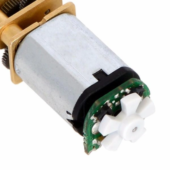
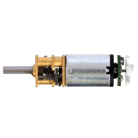
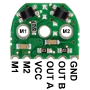
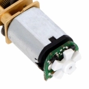
Add quadrature encoders to your micro metal gearmotors (extended back shaft version required) with this kit.The installed system does not exceed the 12 mm × 10 mm cross section of the motors and extends only 5 mm beyond the plastic motor end cap.
The 3-tooth wheel provides 12 counts...
10,00€
Dostupno manje od 5 kom
Jamstvo: 2 godine
Dosegli ste maksimum raspoloživosti - 2
Način plaćanja na web shopu
Jednokratno plaćanje:
- Internet bankarstvo (virman)
- Pouzećem - plaćanje gotovinom dostavljaču kod isporuke paketa
- Maestro, MasterCard, Visa, Visa Premium
Obročno plaćanje:
- MasterCard ZABA do 24 rate
- Visa Premium do 10 rata
10,00€
Opis
Add quadrature encoders to your micro metal gearmotors (extended back shaft version required) with this kit.The installed system does not exceed the 12 mm × 10 mm cross section of the motors and extends only 5 mm beyond the plastic motor end cap.
The 3-tooth wheel provides 12 counts per revolution;
Using the 5-tooth wheel yields 20 counts per revolution.
To compute the encoder counts per revolution of the gearbox output, multiply by the gear ratio
This version is intended for use at 3.3 V.
Because the encoder board outputs are direct phototransistor outputs, some signal conditioning is often necessary
between the sensor and a digital system processing the signals.
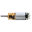
The encoder board is designed to be soldered directly to the back of the motor, with the back shaft of the motor protruding
through the hole in the middle of the circuit board.
The better aligned the board, the better the output signal quality will be. One way to achieve good alignment is to tack down
the board to one motor pin and to solder the other pin only when the board is well aligned.
Be careful to avoid prolonged heating of the motor pins, which could deform the plastic end cap of the motor or the motor brushes.
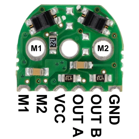
Once the board is soldered down to the two terminals, the motor leads are connected to the M1 and M2
pads along the edge of the board, along with the power for the sensors and the two quadrature outputs
The edge connections are on a 2 mm pitch.
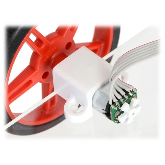
The board can be soldered perpendicularly to another PCB, to a 2 mm connector, or to individual wires
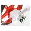
Once the board is soldered to the motor, the plastic encoder wheel can be pushed onto the motor shaft.
The encoder wheel should be pushed on far enough that the gap between the wheel and sensors is approximately 0.5 mm.
One way to get consistent gaps is to use a few sheets of paper or a business card as a shim when installing the encoder wheel.
The best way to confirm optimal placement of the encoder wheel is to look at the signal with an oscilloscope.
The oscilloscope capture shows what the signal outputs look like with the wheel mounted at an optimal distance from the sensors.
Note that even in this optimal case, the signals from the two channels are different due to inherent variations in the two reflectance sensors,
but both signals are 90° out of phase and both span a large voltage range.
Kit contains:
two sensor boards
two 3-tooth encoder wheels
two 5-tooth encoder wheels
Pololu
Pololu je brend koji se ističe svojim visokokvalitetnim elektroničkim komponentama, modulima i robotičkim rješenjima. Pololu je posebno poznat po svojim motorima, senzorima, kontrolerima i drugim elektroničkim komponentama koje se koriste u robotici, automatizaciji, modelarstvu i sličnim područjima. Pololu komponente karakterizira visoka pouzdanost, preciznost i funkcionalnost, što omogućava entuzijastima i profesionalcima da ostvare svoje ideje i projekte. Uz Pololu, dobiti ćeš visokokvalitetne elektroničke komponente koje će ti pomoći u ostvarenju ideja i postizanju izvrsnih rezultata u području elektronike i robotike.

